Introduction
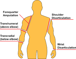
- Human arms are a primary organ that is not only used for sensing and touching objects but also controlling and communication. There are many reasons that a limb can’t be cured and has to be amputated as war, accidental trauma and congenital anomalies. Transradial amputation is the most common one (a surgical procedure in which the radius and bones of the lower arm are cut removed from the body). Transplant or prosthesis are the only options in this case.
- Recently Human interface machines became a part of solving this problem which reads the bio-signals like EOG, EMG, and EEG, and controls an actuator to perform the same tasks of the lost part.
- Because I don’t have any background on the prosthetics the first step in my project was to do a large literature review to see, what is prosthetics? How they are controlled? What normally researchers do in this project? Who are the lead companies in that industry and how do their projects look like?
literature review
- In my project, I will be using the EMG signal. which is generated when the muscles are flexed. Its amplitude depends on the muscle stimulation in a direct proportion way. When the muscle is contracted, the amplitude of the EMG signal on that muscle is high. And when the muscle is relaxed, the amplitude of that signal is low.

- There are two main reasons for choosing the EMG signal. Firstly, it can be easily detected and processed to remove any noise from it as its frequency is about 500Hz. Secondly, it can be detected with some external electrodes so there will be any need to place any electrodes or needles inside the human body.
- The main concept of the project is to create a robotic arm that can be used as a prosthetic arm for an amputee. Any prosthetic has to be able to perform some if not all the functions of the normal organ. Also, it needs to has a low cost.
- For the hand, the main functions are controlling, sensing and communicating. In my project, like most of the prosthetic hand, I will be focusing on controlling the hand Because the human hand has a complex control with many degrees of freedom.
- I found that most companies and researches are trying to do it to provide a robotic arm that is able to perform different types of motions. A better hand is the hand with the higher number of motions that it can perform (but the industrial companies seeks both aesthetics and functionality of the hand here my main concern will be more about controlling the hand).
- What it is usually done in these projects is to place more than one sensor on different body muscles. So, they have many readings from different sensors. And depending on each different reading pattern they make the controller on the hand perform a different motion. This means that more sensors you get. More motions you will have.
- For example in this project, a Bachelor thesis from Metropolia University of Applied Sciences in 2018, they placed three sensors on three different muscles: the forearm muscle, the biceps and the triceps. Depending on those readings, the robotic arm will move. By giving a diverse motion with each different pattern, the arm makes different motions. This process is shown in the below figures.

.common way to control the hand
Methodology
- My project will be mainly focusing on introducing some controlling ways that never existed before. It can be considered more as lab research than to provide a final product that an amputee can use. Also, it is a proof of concept that with only one cheap sensor I can make an arm that does many motions without the need of many sensors on the arm muscles.
- In my project I will not use this way of determining the motion for two reasons. First it requires more than one sensor which means more money as the muscle senor is the most expensive thing in that project and I want my project to be as much cheap as possible. The second reason is that the arm still cannot perform many motions as it still depends on the number of sensors and the way the readings are took.
- In my project I want it to be as much simple as it could for the person who will use the hand, low cost and support infinite number of motions. What I will do is that I will make the arm itself take the decision on what motion to take. The patient will only flex one muscle (I choose that it will be the forearm muscle) and the machine itself determine what is the suitable motion to take at that time object classification algorithms.
- To simplify my project, I will divide it into two stages. The first one is the simple one. In this step I will use an Arduino connected to the muscle sensor and from the reading of the sensor the Arduino will control the motion of the arm. The purpose of that step is to get used to the sensor and the motion of the fingers.
- The second stage which is the advanced stage is that I will use an object classification model and connect a camera to the arm. To let the machine itself determine what is the suitable grip to hold the object in front of it. with that we can increase the number of grips that the hand can perform as we can as the grip now depends on the code we write not the sensors we place.
The sensor I choose to work with is called MyoWare muscle sensor for many reasons. It’s cheap compared to any other sensor and I want the arm to be as much cheap as possible, small in size and this is an important thing because it will be suck on a patient’s hand and The most important that I am not concentrating on determining the EMG pattern and classifying it, I just need something to give me a value when the muscle is flexed because like I said before the machine itself in the project will determine the required motion.

- The arm that I will use to simulate the motion is called inmoov hand. It is an open source hand that can be 3D printed. My college Arwa Hesham will be the responsible of printing and the assembly of the arm. And when the arm is ready I will be responsible of controlling it.

- When I received the sensor the first step was to test it to know its readings. It first required to solder some male pins to it so it can be used with the Arduino(image of the pins).
- Then I used the Arduino analog inputs to know the range of its readings. I stuck it on my forearm and found that the range of the readings when i flex my muscle is about 220 in the analog readings this means that in average my hand produce about 1.2v during the flexing. so in my code i thought about setting a threshold value that the sensor readings can be compared to.
- After knowing the range that my sensor reads and how the analog input is received I started to work in the first stage of my project.
First stage of my project:
- The Arduino code that I will write will do more than one motion. That motion will be determined by the person from his body flexing.
- I will make the hand do three motions from the Arduino code. Those three motions will be as follow relax the hand, do a fest and pointing (will be made by the hand when the arm is ready for controlling meanwhile I will use three LEDs to simulate the motion of the hand).

- The required motion will be determined from the number of flexes that will happen in a period of time. What will happen is that the muscle sensor will be connected to the forearm muscles. And from the number of flexing that the forearm muscle will do it will get the required motion.
- So for example the normal position of the arm will be relaxed. If the person flexed his arm one time the arm will do a fist. But if he flexed his arm for two times fast it will point. And when the arm is creating a fist or pointing, and he flexed the muscle again it will relax.
- The below figure shows what i mean in a given period of time if it was flexed one time it will make a motion if it was flexed two times in a period of time it will do another motion. When the person does the first flex the microcontroller will wait for a time (t) to receive another flex. If he received another flex this means that it requires doing a fist. But if he didn’t receive another thing this means that the arm will point.

- And after doing any of these motions. When the person flex his muscle again the hand returns to the zero position.
- The feast will also be used as a grip to hold objects.
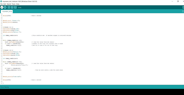
After many trials, removing errors from the code and testing the code this was the final code I got

#define sensorPin  A3                // select the input pin for the sensor signal
#define threshold 170                //the muscle is moving

#define relax 8
#define fist 9
#define point 10

void setup() {
  Serial.begin(9600);           //starting serial commnication
  pinMode(relax,OUTPUT);
  pinMode(fist,OUTPUT);
  pinMode(point,OUTPUT);}


void loop() {

int state=0;                       //shows the number of the signals (the state of the arm)
int val1 = 0;                      // variable to store the value coming from the sensor
int val2 = 0;                      // variable to store the value coming from the sensor
int val3 = 0;                      // variable to store the value coming from the sensor


digitalWrite(relax,HIGH);
Serial.println("motion 0");              //prints that the arm is now relaxing

val1 = analogRead(sensorPin);            // read the value from the sensor
Serial.print("the value =");
Serial.println(val1);                    // print the amplitude of the signal on the serial monitor

if (val1 >= threshold){                  //is the value > the shreshoulf value(the muscle moved)
    state=1;}                            //we recived the first signal

delay(1000);                             //wait a second

if (state ==1){                          //only go through this loop if it reived an initial signal
 for(int i=0;i<500;i++)                 //this loop will see if another signal is recived through two seconds
  { val2 = analogRead(sensorPin);        //start reading from the sensor again quickly
    if (val2 >= threshold){              //if it recived a signal then set the state =2
      state=2;                           //get out of the loop
      i=499;}
    delay(5);}    }


delay(1000);                             //wait a second


Serial.print ("state =");
Serial.println(state);


if(state ==1 ){
 digitalWrite(relax,LOW);
 digitalWrite(fist,HIGH);
 Serial.println("motion 1");

int dummy_comdition=0;                    //this condtion see  if another signal is recieved returns


while (dummy_comdition ==0){
   val3= analogRead(sensorPin);           // read the value from the sensor
   if (val3 >= threshold){                //reamin in the loop till another flex is made
     dummy_comdition =1;}}}               //set dc to true to do out of the loop


if(state ==2 ){
Serial.println("motion 2");
digitalWrite(relax,LOW);
digitalWrite(point,HIGH);

int dummy_comdition=0;

while (dummy_comdition ==0){
   val3= analogRead(sensorPin);           // read the value from the sensor


   if (val3 >= threshold){
     dummy_comdition =1;}}}                    //now we will write a code for each state


Serial.println("code end");
delay(1000);                             //wait a second


}- I will discuss the main parts of the code
- At the beginning there’s a threshold value that is set to 170. This threshold value will be compared to the readings of the sensor. So, it will determines when the muscle is flexed when the sensor reading is more than 170.
- Like I said before there will be three motions that the hand will do. Now the hand that I will test on it isn’t ready so instead I will use three LEDs when each LED illuminate this means that this particular motion is achieved.
- There is a variable named state which will determine the motion that the hand will perform. And there are three loops in the code. Those are the main parts of the code.
- At the beginning of the code the state is set to zero which means that the hand is in the relax state. the void loop will keep running. In each run it will take the reading of the sensor (line 27) and compare it with the threshold value that I set before (line 31).
- When the value is more than the threshold value this means that the person flexed the muscle. And this will set state to 1(line 32).
- When state is set to 1 the code will run the first loop (line 36). This loop will run 500 time this will take two seconds because of the delay that is inside the code (line 41). in each loop it will read the sensor value if it exceeded the threshold again (this means that the person flexed his muscle again) it will set the state to 2(line 40). If the person didn’t flex the muscle again the state will remain 1 and the two seconds will just pass.
- After those two loops. Depending on the value of the state the code will run the second or the third loop (line 52 and line 66).
- Both loops have the same sequence, they are just having different outputs.
- For example, the what the first loop do is it set the lap that indicates the fist on (later this will change to the motion of the hand to the fist position). Then it will enter another nested loop. This second loop will run infinitely. In each iteration it will read the sensor signal again till the person flex his muscles again it will break put of the loop and make the hand relax again and set everything to the beginning and start the code all over again.
- the below video shows the code working with the muscle sensor. the three motions were formed on LEDs. each led shows a motion that the arm will perform.
- This was the first step of my project.
- With this method I got three different motions with only one sensor and the patient will not need to be trained to set different muscles together.
- The next step of the project will be to connect a camera and create a new program that classify the objects that the camera see. So, the hand can change the grip depending on the object that is in front of it.
Second stage
- At the beginning I need to use a CNN Architecture (Convolutional Neural Network). Which are a kind of multilayer neural network that are designed to recognize the visual patterns directly from pixel images. In other words classify what is inside the image.
- There are many of these architectures that are available like LeNet, AlexNet, ResNet, GoogLeNet, VGG and more.
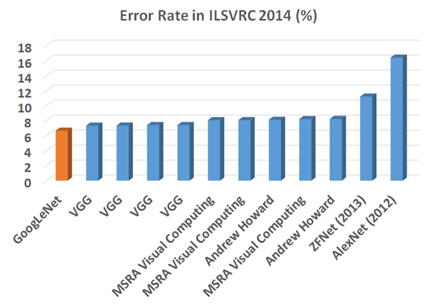
- After a deep searching and reviewing many opinions. The one I chose to work with is GoogLeNet model because of the features I found in. its also the winner of ILSVRC (ImageNet Large Scale Visual Recognition Competition) in 2014. Which is an image classification competition that is held every year. It achieved a top-5 error rate of 6.67% This is very close to human level performance.
- This link https://medium.com/coinmonks/paper-review-of-googlenet-inception-v1-winner-of-ilsvlc-2014-image-classification-c2b3565a64e7?fbclid=IwAR2rpNeowPJGCCEx_kdV1YhrmXM5y7sCGkAOTQeOb2xJctlhg94krS2jygs talks about some features of this model and how it can process with less calculations and the The 1×1 Convolution that was used with this model. it also discuss some of this model features like Inception Module, Global Average Pooling, Overall Architecture, Auxiliary Classifiers for Training, Testing Details. And what is meant by each of them.
- This model is found on github here https://github.com/opencv/opencv_extra/blob/master/testdata/dnn/bvlc_googlenet.prototxt
- This pre-trained model can detect 1000 class that are found here also on gethub.
https://github.com/opencv/opencv/blob/master/samples/data/dnn/classification_classes_ILSVRC2012.txt
- The next step now is to train this model to detect what the camera that is next to the hand to see.
- The programing that I will write for that task will be written in python. I choose python to do this because of its easy syntax and its easily to access camera from it.
- I will also use OpenCV (open computer vision) which is the most known library when it comes to image processing and object classification. It was firstly developed by intel and its free license is open source.
- https://docs.opencv.org/3.4/index.html this is the main site of the library. It includes many tutorials, examples and modules describing everything you need to use with this library starting from how to setup the library till how to create many projects with it.
- After deep research on how to train the mode to do a certain task in python and how to use OpenCV library with this it was the time to write my own program that will train this pretrained model to detect the 1000 object.
- After many trials, debugging and removing errors. This was my first program to write

- Now I will explain the sequence of the code.
- First I include the OpenCV library and numpy library (library that is used for matrix calculatoins)
- Then I include the GoogLENET model that will be used. Its basically formed from two files which are (.caffemodel) and (.txt) and we will use a function called cv2.dnn.readnetformat that reads the format of the model and named it net (line 7).
- Now I opened the file that includes the 1000 class that will be detected to determine the name of the object when it is detected (line 9 and line 10).
- Then we will start the video recording. I will be usine the default camera of the laptop (number zero) for just now (line 11).
- Then we start the continues loop of the controller (line 13).
- We take a frame from the camera then we need to resize this frame to the required size by the model (line 15 and line 17).
- Then we send this frame to the model to be compared with the 1000 class that it has (lines 19 and 20)
- Then the output of this process is received from a function named net.forward and I will store them in a variable named classification (line 20).
- Classification will be an array formed from 1000 item in each index there is a probability came from the comparison of the items we have in our frame with the 1000 class that this model has. Most of the numbers will be in range of zero because they didn’t match most of the classes and it only matched one class.
- Now we will use a function called cv2.MaxMinLoc. what this function basically return is four things. The location of the highest number in that array and its value. The location of the lowest number and its value.
- So, basically four things. But we don’t need the location and value of the minimum values. We just need the high ones cause they represent the highest probability that this object in the frame is classified as one of the 1000 class
- But also, all objects that was inside the frame wasn’t similar to any of the classes we have and the highest probability we have is in range of 0 (for example in range 10^-5). That is why we will need another filter that will assure that the highest probability we got is in a suitable range.
- That is why the condition in line 27 was made. It see if the probability was higher than 20% then we will accept it. if it was less than this its not accepted. The reason why I used 20% was just trying and error. At the beginning I used to print the highest probability value and I found that in most of the time when the readings range are more than 20% the object is determined correctly.
- Then if it was true we get the name of the object from the text file named lines that I wrote before and print it on the video (line 29 and 30). Else it was less than 0.2 then print unknown and finally print the frame on the screen to appear as a video (line 38) then clear all the data and start the loop again.
Those are some screenshots of this code while it is working

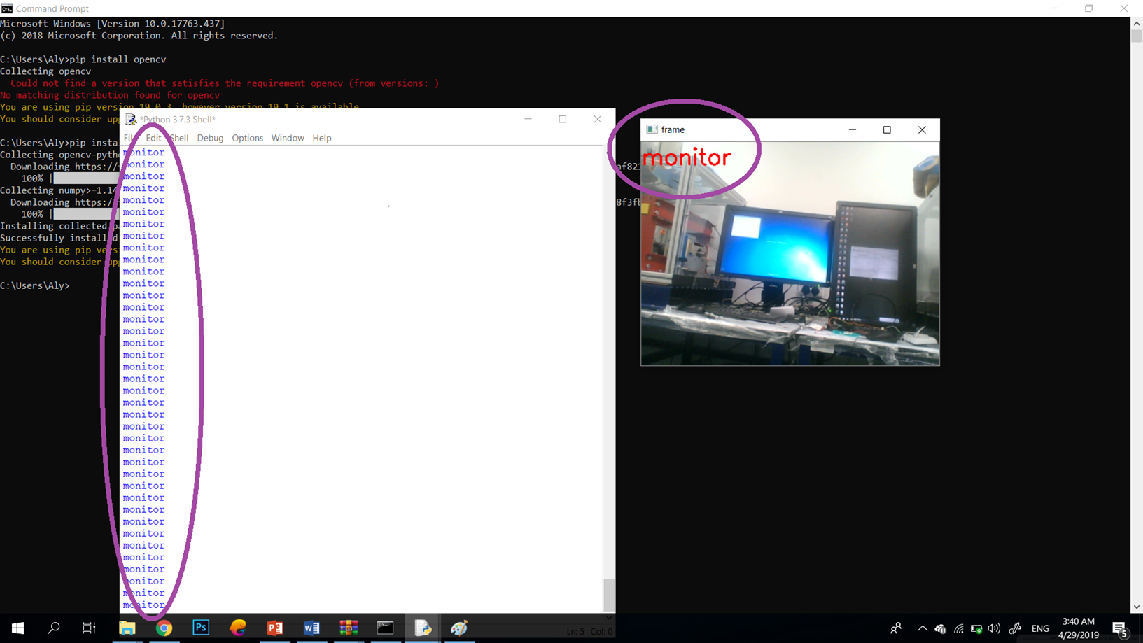

- And there are many other things that it can detect.
- Now I have a working Arduino code and a working python code. We will need now to link them together. I need the classifications that appears on the screen to be sent to the Arduino to control how the hand will hold that object.
- So what will happen is that the python will only be responsible to determine the object and continually send the object’s name to the Arduino. And the Arduino will be connected to the muscle sensor to detect its readings. And when the person flex his hand the robotic arm will close in a way to hold the object that it already know what is it.
- That means that I have to connect the two codes together.
Combining the two codes
- There is a communication library that I found designed for this purpose. It starts a serial communication between the python and the Arduino with the baud rate that you determine in both.
- This library is called pyserial 3.4 that can be downloaded from the ink https://pypi.org/project/pyserial/#files
- And this was the python code after adding the library and doing some modifications.


import cv2
import numpy as np
import serial

ard = serial.Serial('com23',9600)

model = "bvlc_googlenet.caffemodel"
protxt = "bvlc_googlenet.prototxt.txt"

net = cv2.dnn.readNetFromCaffe(protxt,model)

text_file = open("classification_classes_ILSVRC2012.txt","r")
lines = text_file.readlines()

cap = cv2.VideoCapture(0)

while True:

        ret,frame = cap.read()

        model_frame = cv2.resize(frame , (224,224) )
        blobfromImage = cv2.dnn.blobFromImage( model_frame , 1 , (224,224) )
        net.setInput(blobfromImage)
        classifications = net.forward()

        min_value,max_value,min_loc,max_loc = cv2.minMaxLoc(classifications)

        class_probability = max_value
        class_number = max_loc

        if class_probability > 0.2:

            label = lines[ class_number[0] ][0:-1]
            print(label)

            if(label == 'coffee mug'):
                ard.write(b'1')

            elif(label == 'water bottle'):
                ard.write(b'2')

            elif(label == 'cup'):
                ard.write(b'3')

            elif(label == 'iPod'):
                ard.write(b'4')


            elif(label == 'cellular telephone, cellular phone, cellphone, cell, mobile phone'):
                ard.write(b'5')


            else:
                ard.write(b'0')


            cv2.putText(frame,label,(0,30),cv2.FONT_HERSHEY_SIMPLEX,1,(0,0,255),2)

        else:

            label = "unknown"

        cv2.imshow("frame",frame)
        key = cv2.waitKey(1)& 0xFF
        if key == ord("q"):
                break
cv2.destroyAllWindows()- The library work pretty simple you need just to define the port that the Arduino is connected to and define the baud rate and using a simple function you send characters to the ardunio.
- I will test the system at the beginning using some objects like if the object that was in front of the camera is a coffee mug,it will send the Arduino 1. If it was water bottle it will send 2. If it was cup it will send 3, if it was an ipod it will send 3. If it was a cell phone it will send 3. If it was another object it will send 0.
- And the Arduino will do a different motion depending on what is sent to it.
- This was the Arduino code that I created to do this task. Basically it is connected to five different LEDs it will light one depending on the reading on the object in front of the camera.

- This code is pretty simple. It just waits till it receives the object reading for ten times successively the it witch on the lamp that simulate that object.
- Those video shows the code working. what happens in those videos is that when an object is set in front of the camera the Arduino will produce a different output and set a specific led to high depending on this object.
- Now I merged this code with the muscle sensor code so when the person flexes his hand the arm will be closed but also depending on what is in front of the camera.


- Those are the final two codes that I have
- This is the time now to start working on the hardware part. To control the inmoov hand instead of the LEDs.
Starting to control the hand
- My colleague Arwa and I cooperated to complete the final step of the project. Firstly, I put the the servos in its place. and connected the wires that will move the fingers.
- In the inmoov hand, the way of controlling the fingers motion is by two wires connected to a servo motor. Therefore, if the servo motor rotated in a certain direction the finger will open and if it rotates in the opposite direction the finger close.
- Four of the five servos I have got were not working. There was not enough time to replace the four non-working servos. So, as a proof of concept, I used the only working servo I had to open and close one finger and I also merged the servo control code with the sensor code.
- This video shows what I did. When I give the sensor the first motion the arm will be closed and when I give it the motion number zero the finger will be opened.
- At the end of my project, even if i did not have time to do the final control of the arm I created a code to merge between the different stages of the project. I had the code that moves the arm depending on the received EMG signals, also the part that receives the object that the camera sees in front of the hand and the part that can control the servos. As I said before, the main aim of this project was to make a new way for controlling the hand with the EMG signals that does not depend on the number or the accuracy of the muscle sensor readings.
Conclusion
Hands are primary organs in the human body. When it is lost and the only solution is using prosthetic hand, it will be more helpful to have a prosthetic hand that will help in living a normal life. the hand needs to cover all amputee’s needs. So, instead of teaching the amputee how to use it and just focus on how to make him able to control every part of the hand. It will be more efficient it the hand itself was intelligent and able to cover the amputee’s needs with itself.
Reflections
At the beginning of the project, I did not know much about the prosthetic arms, how they are controlled, what an EMG signals are. I had previous experience using python coding but this was the first time I used OpenCV and used a deep learning model for object classification. I learned many things with this project, for example, how to develop a python code that can access the camera, detect objects and communicate with Arduino.
The next steps in this project will to be able to control the hand with new servo motors and to identify many motions for the hand in order to grab different objects.

